symcad
What is SymCAD?
SymCAD is a Python library that combines symbolic model creation, orientation, and assembly with concrete CAD representations and manipulations. It allows users to programmatically design individual shape-based parts, ranging from the very simple and generic to the complex and specific, while allowing parameters related to the geometry, orientation, and placement of a part to be expressed symbolically.
Notable features of the library include:
- Utilizes the Python sympy library for symbolic manipulation of parameters
- Utilizes the FreeCAD Python backend for CAD file processing and manipulation
- Works with both scripted and modeled CAD designs
- Provides two methods of model construction:
- Assembly-by-Placement: Part placement is explicitly defined
- Assembly-by-Attachment: Part placement is implicit based on rigidly attached parts
- Includes a built-in library of generic parts
- JSON-based Graph API for design representation
- Specification of center-of-placement/origin for each part
- Custom attachment and connection points for each part
- Part-based physical property retrieval:
- Based on closed-form equations (concrete or symbolic)
- Based on CAD representations (concrete)
- Based on pretrained neural networks (concrete or symbolic)
- Assembly-based cumulative physical property retrieval
- Physical properties include: mass, material volume, displaced volume, surface area, center of gravity, center of buoyancy, length, width, and height
- Part importation from existing CAD models (FreeCAD, STEP, or STL)
- Interference detection for parts within an assembly
- Easy-to-create custom parts (scripted or modeled)
- Automatic separation of regular and displacement models
- Parts and assemblies exportable to FreeCAD, STEP, or STL
- State-based physical properties for assemblies
- Simple interface for concretizing free parameters in a symbolic design
- Symbolic parameters can auto-combine or concretize based on attachments (TODO)
- Auto-generated and updated documentation upon GitHub commit
Terminology and Conventions
Important terms used by the SymCAD library include:
- Part/Component/Shape: Used interchangeably to refer to a single atomic shape that is
represented by an object extending the
SymPartclass, containing its own set of physical geometric properties and placements - Assembly: A collection of parts along with their respective global placements and/or attachments
- Attachment: A physical, rigid joining of two parts (i.e., if one part moves or is rotated, its attachments will also move or rotate)
- Connection: A flexible or logical (non-physical) joining of two parts (i.e., if one part moves, it does not affect its connections)
- Origin: Used interchangebly with "Center of Rotation" or "Placement Center" to indicate the location on a part which serves as its center of placement as well as the point around which it rotates
Internal conventions assumed by the library are as follows:
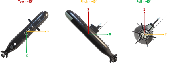
Coordinate systems: All coordinate systems in this library are relative to their enclosed parts and adhere to the following conventions: Each x-axis has its origin at the front of a given part and extends positively toward the rear. Each y-axis has its origin at the left of the part when looking from the positive x-axis toward origin and extends positively to the right. Each z-axis has its origin at the bottom of the part and extends positively upward. The following images illustrate this, using a UUV fairing as the basis:

- Local coordinate system: The coordinate system used internally by each part to indicate
the locations of its attachment and connection points, as well
as its center of placement and rotation. All coordinates fall
within the range
[0.0, 1.0]and are relative to the total length (x-axis), width (y-axis), and height (z-axis) of the part. This coordinate system rotates along with the part. - Global coordinate system: The coordinate system used by an assembly to place and orient its constituent parts. It does not rotate, and its coordinates represent global placements in units of meters.
- Units: Unless otherwise specified, all measurements are represented in base SI units (e.g.,
meters, celcius, grams). Notable exceptions include mass (
kg) and any measurements involving mass (e.g., density =kg/m^3). - Orientation: Refers to the final rotation of a part in the global coordinate system according to the nautical and aviation convention of intrinsic, right-handed rotations using the yaw-pitch-roll rotation order. This corresponds to first rotating about the z-axis, followed by the y-axis, followed by the x-axis. These angles are also called Tait-Bryan angles (related to Euler angles). For convenience, any orientation may also be specified using a rotation matrix or a quaternion.
- Yaw: Refers to the rotation of a part around the z-axis. A positive yaw angle represents a counter-clockwise rotation when looking from the positive z-axis toward origin (i.e., a vehicle veering to the left from the point of view of a person inside the vehicle).
- Pitch: Refers to the rotation of a part around the y-axis. A positive pitch angle represents a counter-clockwise rotation when looking from the positive y-axis toward origin (i.e., the nose of a vehicle pitching downward).
Roll: Refers to the rotation of a part around the x-axis. A positive roll angle represents a counter-clockwise rotation when looking from the positive x-axis toward origin (i.e., a vehicle tilting to the left from the point of view of a person inside the vehicle).
- Default orientation: If not explicitly defined, the default orientation of a part will be
(0, 0, 0), indicating no change from its default orientation. - Default material density: If not explicitly defined upon creation of a part, a material
density of
1.0 kg/m^3will be assumed (which may result in incorrect calculations for the mass of a part). - Default origin: Unless explicitly set, the default origin/center-of-rotation of a part will be treated symbolically.
- Default placement: Unless explicitly set, the default placement of a part will be treated symbolically.
- Part geometry: The geometric representation of each part is completely unique to the part
and is determined by either its
SymPartclass implementation or its underlying CAD model, depending on how the part was created. In either case, theset_geometry()method for a given part will always specify a set of keywords indicating its precise underlying geometric properties.
Specific details regarding the geometric parameters and default orientation of any SymCAD part
can be found in its corresponding part-specific documentation page.
Getting Started
To use the SymCAD library in your project, you may install it manually using the string
git+https://github.com/SymBench/SymCAD.git with pip or add it as a dependency in your
requirements.txt file. Alternately, you may add the GitHub repository as a submodule to your
project using git submodule add https://github.com/SymBench/SymCAD. If you plan to develop or
work on the SymCAD project itself, you should clone the
SymCAD repository and install it using
python3 -m pip install -e . from the SymCAD root directory.
Once the library has been installed, you may begin work on your first SymCAD assembly as shown in the following example:
from symcad.core import Assembly
from symcad.parts import Pipe, FlangedFlatPlate, Torisphere

# Create random concrete components
front_endcap = FlangedFlatPlate('FrontEndcap')\
   .set_geometry(radius_m=0.22, thickness_m=0.08)\
   .set_orientation(roll_deg=0, pitch_deg=-90.0, yaw_deg=0)\
   .add_attachment_point('EndcapAttachment', x=0.5, y=0.5, z=0)
center_pipe = Pipe('CenterPipe')\
   .set_geometry(radius_m=0.22, height_m=0.6, thickness_m=0.0025)\
   .set_orientation(roll_deg=0, pitch_deg=90.0, yaw_deg=0)\
   .add_attachment_point('AttachmentFront', x=0.5, y=0.5, z=0)\
   .add_attachment_point('AttachmentRear', x=0.5, y=0.5, z=1)
rear_endcap = Torisphere('RearEndcap')\
   .set_geometry(base_radius_m=0.22, thickness_m=0.0025)\
   .set_orientation(roll_deg=0, pitch_deg=90.0, yaw_deg=0)\
   .add_attachment_point('EndcapAttachment', x=0.5, y=0.5, z=0)

# Create assembly using attachments
assembly = Assembly('SymCadExample')
center_pipe.attach('AttachmentFront', front_endcap, 'EndcapAttachment')\
           .attach('AttachmentRear', rear_endcap, 'EndcapAttachment')
assembly.add_part(front_endcap)
assembly.add_part(center_pipe)
assembly.add_part(rear_endcap)

# Globally place the front_endcap and export the CAD assembly
front_endcap.set_placement(placement=(0, 0, 0), local_origin=(0.5, 0.5, 1))
assembly.export('assembly_example.FCStd', 'freecad')
In the example just shown, a FreeCAD model is generated using parts with fully concrete geometries,
orientations, and placements. In many cases, these parameters may need to remain symbolic (e.g.,
creating a Pressure Vessel for an underwater vehicle where the material thickness of the part
depends on the maximum target vehicle depth, and its length may be depend on the number of
batteries being stored inside). In this case, these parameters may be kept symbolic by simply
not calling the respective set_XXX methods on the relevant part, or, if you must use these
methods (for example, to concretely set only some of the geometric parameters), you may keep
non-concrete parameters symbolic by passing them a value of None:
from symcad.core import Assembly
from symcad.parts import Pipe, FlangedFlatPlate, Torisphere

# Create random concrete components with symbolic geometries
front_endcap = FlangedFlatPlate('FrontEndcap')\
   .set_geometry(radius_m=None, thickness_m=0.08)\
   .set_orientation(roll_deg=0, pitch_deg=-90.0, yaw_deg=0)\
   .add_attachment_point('EndcapAttachment', x=0.5, y=0.5, z=0)
center_pipe = Pipe('CenterPipe')\
   .set_orientation(roll_deg=0, pitch_deg=90.0, yaw_deg=0)\
   .add_attachment_point('AttachmentFront', x=0.5, y=0.5, z=0)\
   .add_attachment_point('AttachmentRear', x=0.5, y=0.5, z=1)
rear_endcap = Torisphere('RearEndcap')\
   .set_geometry(base_radius_m=None, thickness_m=0.0025)\
   .set_orientation(roll_deg=0, pitch_deg=90.0, yaw_deg=0)\
   .add_attachment_point('EndcapAttachment', x=0.5, y=0.5, z=0)

# Create assembly using attachments
assembly = Assembly('SymCadExample')
center_pipe.attach('AttachmentFront', front_endcap, 'EndcapAttachment')\
           .attach('AttachmentRear', rear_endcap, 'EndcapAttachment')
assembly.add_part(front_endcap)
assembly.add_part(center_pipe)
assembly.add_part(rear_endcap)

# Globally place the front_endcap and and output the remaining free parameters
front_endcap.set_placement(placement=(0, 0, 0), local_origin=(0.5, 0.5, 1))
print('Free Parameters:', assembly.get_free_parameters())
This should print out the following list of symbolic free parameters:
Free Parameters: ['CenterPipe_height', 'CenterPipe_radius', 'CenterPipe_thickness',
                  'FrontEndcap_radius', 'RearEndcap_base_radius']
Note that attempting to retrieve the physical properties of an assembly containing symbolic parameters will return those properties as symbolic equations with respect to any remaining free parameters, like so:
print('Displaced Volume:', assembly.displaced_volume())
which should output a large equation with respect to the free parameters listed above. This is useful when utilizing either a single part or an entire assembly to maintain some constraint; for example, when using the SymBench Constraint Solver to ensure that a Pressure Vessel has a large enough volume to contain the necessary number of battery cells or to ensure that an assembly has coincident centers of buoyancy and gravity, offset only by some z-axis value:
# Create battery volume constraint
required_battery_cell_volume = 1.23  # Calculation done elsewhere
pressure_vessel.displaced_volume() >= required_battery_cell_volume

# Create center of gravity and buoyancy constraints
uuv_assembly.center_of_gravity().x == uuv_assembly.center_of_buoyancy().x
uuv_assembly.center_of_gravity().y == uuv_assembly.center_of_buoyancy().y
uuv_assembly.center_of_gravity().z <= uuv_assembly.center_of_buoyancy().z
To add to the utility of the above symbolic physical properties, it is also possible to specify that an external symbol or equation should be used for any of the geometric, orientation, or placement parameters of a part. For example, instead of making the entire geometry of the previously shown Pressure Vessel independently symbolic, we could specify that its radius is equal to a symbolic fairing radius, and its thickness is equal to some complex model-based equation that depends on a target depth:
# These symbols and equations could be defined elsewhere or retrieved
# from some other component or SymPart
fairing_radius = sympy.Symbol('fairing_radius_m')
maximum_depth = sympy.Symbol('maximum_depth_m')
material_thickness_model = ThicknessModel()  # Defined elsewhere
material_thickness = material_thickness_model.get_thickness_at(maximum_depth)

pressure_vessel.set_geometry(radius_m=fairing_radius, thickness_m=material_thickness)
The output of retrieving a physical property from the above Pressure Vessel would then be an equation that depends (at least partially) on the maximum target vehicle depth and the total fairing radius of the underwater vehicle.
Once concrete values have been determined for the available free parameters in an assembly, they can be passed or loaded into that assembly using the following method to enable a fully defined CAD model to be generated, along with its concretely defined physical properties:
from symcad.core import Assembly
from symcad.parts import Sphere

# Define an assembly containing a single symbolic sphere
sphere = Sphere('RandomSphere')
assembly = Assembly('ExampleAssembly')
assembly.add_part(sphere)

# Create a dict of `free parameter: concrete value` pairs
#    These values should be solved for externally and loaded here
concrete_params = {
  'RandomSphere_origin_x': 0.5,
  'RandomSphere_origin_y': 0.5,
  'RandomSphere_origin_z': 0.5,
  'RandomSphere_placement_x': 0.1,
  'RandomSphere_placement_y': 0.0,
  'RandomSphere_placement_z': 0.0,
  'RandomSphere_radius': 0.2
}

# Generate the concrete assembly
concrete_assembly = assembly.make_concrete(concrete_params)

# Output some physical properties of the assembly using its model equations
print(concrete_assembly.displaced_volume())
print(concrete_assembly.center_of_gravity())

# Output the physical properties of the assembly as determined from its CAD model
print(concrete_assembly.get_cad_physical_properties())

# Export the CAD model as an STL file
concrete_assembly.export('concrete_test.stl', 'stl')
All of the previous examples show construction of a design using
Assembly-by-Attachment; however,
it is also possible to construct a concrete design using
Assembly-by-Placement which ignores the
entire attachment and connection subsystem of the library. In this mode of operation, you simply
create individual parts and opt not to call any of their add_attachment_point(), attach(),
add_connection_port(), or connect() methods:
from symcad.core import Assembly
from symcad.parts import Pipe, FlangedFlatPlate, Torisphere

# Create random components
front_endcap = FlangedFlatPlate('FrontEndcap')\
   .set_geometry(radius_m=0.22, thickness_m=0.08)\
   .set_orientation(roll_deg=0, pitch_deg=-90.0, yaw_deg=0)
center_pipe = Pipe('CenterPipe')\
   .set_geometry(radius_m=0.22, height_m=0.6, thickness_m=0.0025)\
   .set_orientation(roll_deg=0, pitch_deg=90.0, yaw_deg=0)
rear_endcap = Torisphere('RearEndcap')\
   .set_geometry(base_radius_m=0.22, thickness_m=0.0025)\
   .set_orientation(roll_deg=0, pitch_deg=90.0, yaw_deg=0)

# Create an assembly without any attachments
assembly = Assembly('SymCadExample')
assembly.add_part(front_endcap)
assembly.add_part(center_pipe)
assembly.add_part(rear_endcap)

# Manually place all components in the assembly (or solve for them externally)
front_endcap.set_placement(placement=(0, 0, 0), local_origin=(0.5, 0.5, 1))
center_pipe.set_placement(placement=(0.08, 0, 0), local_origin=(0.5, 0.5, 0))
rear_endcap.set_placement(placement=(0.68, 0, 0), local_origin=(0.5, 0.5, 0))
assembly.export('assembly_by_placement_example.FCStd', 'freecad')
In this case, the placement of all parts will remain symbolic, and each part origin and placement coordinate:
- will appear as an additional free parameter in each physical property equation, and
- can be concretized in exactly the same manner as the geometric properties shown above.
Of course, a hybrid approach may be taken whereby some parts are placed via Assembly-by-Attachment and other parts are left to Assembly-by-Placement for the final concrete CAD representation.
Additional usage examples may be found in the SymCAD Repository
under the examples directory.
How do I ...
... create a new scripted SymCAD part?
A scripted SymCAD part is a part whose CAD representation is generated programmatically using the FreeCAD Python backend. A discussion of the FreeCAD API is beyond the scope of this project, but many examples can be found online in the official documentation or via search engine.
In order to create a part that uses this backend, you must simply create a Python class that
inherits from the symcad.core.SymPart class, and create a method in your class definition with the following
signature:
@staticmethod
def your_method_name(params: Dict[str, float], fully_displace: bool) -> Part.Solid:
where the params dictionary specifies the mapping between a symbolic geometric property in your
part and its desired concrete value, the fully_displace boolean specifies whether a
displacement model should be created, and a FreeCAD Part.Solid is returned. The contents of the
method are entirely up to you.
As an example, the following code is used to generate the CAD model for a paremetric 3D box:
from PyFreeCAD.FreeCAD import FreeCAD, Part

@staticmethod
def __create_cad__(params: Dict[str, float], fully_displace: bool) -> Part.Solid:
   thickness_mm = 1000.0 * params['thickness']
   outer_length_mm = 1000.0 * params['length']
   outer_width_mm = 1000.0 * params['width']
   outer_height_mm = 1000.0 * params['height']
   inner_length_mm = outer_length_mm - (2.0 * thickness_mm)
   inner_width_mm = outer_width_mm - (2.0 * thickness_mm)
   inner_height_mm = outer_height_mm - (2.0 * thickness_mm)
   outer = Part.makeBox(outer_length_mm, outer_width_mm, outer_height_mm)
   inner = Part.makeBox(inner_length_mm, inner_width_mm, inner_height_mm,
                        FreeCAD.Vector(thickness_mm, thickness_mm, thickness_mm))
   return outer if fully_displace else outer.cut(inner)
This method is passed to the cad_model parameter of the __init__() function of the
symcad.core.SymPart class from which your custom part must inherit:
from PyFreeCAD.FreeCAD import FreeCAD, Part
from symcad.core.SymPart import SymPart
from sympy import Symbol, Expr

class MyCustomBox(SymPart):

   def __init__(self, identifier: str, material_density_kg_m3: float):
      super().__init__(identifier, self.__create_cad__, None, material_density_kg_m3)
      setattr(self.geometry, 'length', Symbol(self.name + '_length'))
      setattr(self.geometry, 'width', Symbol(self.name + '_width'))
      setattr(self.geometry, 'height', Symbol(self.name + '_height'))
      setattr(self.geometry, 'thickness', Symbol(self.name + '_thickness'))

   @staticmethod
   def __create_cad__(params: dict, fully_displace: bool) -> Part.Solid:
      thickness_mm = 1000.0 * params['thickness']
      outer_length_mm = 1000.0 * params['length']
      outer_width_mm = 1000.0 * params['width']
      outer_height_mm = 1000.0 * params['height']
      inner_length_mm = outer_length_mm - (2.0 * thickness_mm)
      inner_width_mm = outer_width_mm - (2.0 * thickness_mm)
      inner_height_mm = outer_height_mm - (2.0 * thickness_mm)
      outer = Part.makeBox(outer_length_mm, outer_width_mm, outer_height_mm)
      inner = Part.makeBox(inner_length_mm, inner_width_mm, inner_height_mm,
                           FreeCAD.Vector(thickness_mm, thickness_mm, thickness_mm))
      return outer if fully_displace else outer.cut(inner)
Additionally, your new SymCAD part class must implement the following abstract methods from the
symcad.core.SymPart parent class with the appropriate symbolic formulas for your new part:
@property
def material_volume(self) -> Union[float, Expr]:

@property
def displaced_volume(self) -> Union[float, Expr]:

@property
def surface_area(self) -> Union[float, Expr]:

@property
def unoriented_center_of_gravity(self) -> Tuple[Union[float, Expr], Union[float, Expr], Union[float, Expr]]:

@property
def unoriented_center_of_buoyancy(self) -> Tuple[Union[float, Expr], Union[float, Expr], Union[float, Expr]]:

@property
def unoriented_length(self) -> Union[float, Expr]:

@property
def unoriented_width(self) -> Union[float, Expr]:

@property
def unoriented_height(self) -> Union[float, Expr]:
Finally, a set_geometry(self, **kwargs) method must be implemented by your custom SymCAD part
to set any symbolic parameters to their concrete values (or None if they should remain symbolic):
def set_geometry(self, *, length_m: Union[float, None],
                          width_m: Union[float, None],
                          height_m: Union[float, None],
                          thickness_m: Union[float, None]) -> MyCustomBox:
   self.geometry.set(length=length_m, width=width_m, height=height_m, thickness=thickness_m)
   return self
For a full example of the custom 3D box just described, refer to scripted_symcad_part.py in the
examples directory of the SymCAD Repository.
... create a new modeled SymCAD part?
A modeled SymCAD part is a part whose CAD representation is pre-created by the user in the
FreeCAD format and stored in the src/symcad/cadmodels/[X] directory (where X is the directory
or directory tree to which the CAD model belongs).
Any type of CAD model internal structure is supported; however a number of conventions must be satisfied:
- The root label of the base part must be 'Model'
- The root label of the displacement part (if it exists) must be 'DisplacedModel'
- If the model is parameteric, the parameters must be stored in an internal spreadsheet with the label 'Parameters'
- The first column of the 'Parameters' spreadsheet should be a description of the parameter, the second column should be the default value of the parameter (can be anything), and each value should have an alias assigned to it that is used by the CAD model to alter its geometry.
- Any extra or derived non-public parameters should be specified in the spreadsheet underneath a row with a cell containing the word 'Derived' below all other public geometric parameters.
After creation and storage of the CAD model, its base file name is passed to the cad_model
parameter of the __init__() function of the symcad.core.SymPart class from which your custom
part must inherit. All other implementation details remain the same as described above for part
creation using a scripted SymCAD approach. Refer to the
modeled_symcad_part.py file under the examples directory of the
SymCAD Repository for an example of a custom modeled
SymCAD part.
... import an existing CAD model?
An existing CAD model can be imported and used as a SymPart within SymCAD as if it were a
built-in part by using the symcad.parts.generic.Custom class. If the existing CAD model is in
the FreeCAD format and follows the rules outlined in the
previous section, the model can even be parametric and
contain symbolic free parameters. For example, to use an existing CAD model stored at
/tmp/Existing.stp as if it were a built-in symcad.core.SymPart, you can use any of the
following templates:
from symcad.parts import Custom

custom_shape = Custom('Custom', 'Shape', '/tmp/Existing.stp')
custom_shape_with_neural_net = Custom('Custom', 'ShapeWithNN', '/tmp/Existing.stp', '/tmp/ExistingNN.tar.xz')
custom_shape_with_density = Custom('Custom', 'ShapeWithDensity', '/tmp/Existing.stp', None, 1028.0)
The symcad.parts.generic.Custom SymPart class can also be used to create a custom part based on
a scripted CAD representation. This is achieved by passing a static CAD creation method to the
symcad.parts.generic.Custom initializer as described in the
scripted SymCAD section:
from PyFreeCAD.FreeCAD import FreeCAD, Part
from symcad.parts import Custom

def cad_creation_method(params: dict, fully_displace: bool) -> Part.Solid:
   # Your implementation here

custom_shape = Custom('Custom', 'Shape', cad_creation_method)
Once created, an imported Custom part behaves exactly the same as any other SymPart in the
library.
Note, if an existing parametric CAD model is imported but no corresponding neural network is
specified to represent a mapping between the geometric parameters of the part and its
mass/physical properties, a neural network will automatically be trained to learn these mappings
unless a value of False is passed to the auto_train_missing_property_model parameter of the
symcad.parts.generic.Custom constructor. This operation can take quite some time, so it is
recommended that this be done when you are not expecting to continue working with SymCAD for
awhile. Once trained, the neural network will be stored for later retrieval so that the training
process does not have to be repeated again in the future.
... retrieve physical properties from a part?
The following list of physical properties may be retrieved from a SymCAD part at any time by simply requesting the property method on the corresponding part:
- mass
- material volume
- displaced volume
- surface area
- unoriented center of gravity
- oriented center of gravity
- unoriented center of buoyancy
- oriented center of buoyancy
- unoriented length
- oriented length
- unoriented width
- oriented width
- unoriented height
- oriented height
# Example of accessing some physical properties for a part
print('Displaced Volume:', part.displaced_volume)
print('Center of Gravity (Unoriented):', part.unoriented_center_of_gravity)
For properties that contain both an oriented and an unoriented version, the unoriented
version will return the corresponding property as if the part were created with an orientation
of 0° yaw, 0° pitch, and 0° roll. The oriented version will return the
corresponding property using the orientation of the underlying part as specified by the user
(even if that orientation is symbolic).
... create an assembly using Assembly-by-Placement?
Assembly-by-Placement is used to allow for complete control over the precise placement and
orientation of every part within an assembly (represented by the symcad.core.Assembly class).
This mode is the default for all SymPart components for which none of the
add_attachment_point(), attach(), add_connection_port(), or connect() methods have
been called. In this case, the placement of a part will be represented by three symbolic
parameters representing the origin/center-of-placement of the part in its own coordinate
space, as well as three additional symbolic coordinates representing the placement of the
origin of the part in the global coordinate space.
The coordinates for the origin of the part are expected to fall in the range [0.0, 1.0] and
are relative to the x-axis length, y-axis width, and z-axis height of the part. The coordinates
for the global placement of the part are absolute measurements in units of meters. If one or
more of these parameters should be set to a concrete value while the other parameters remain
symbolic, the set_placement() method may be called with a value of None for all parameters
which are intended to remain symbolic:
concrete_part.set_placement(placement=(None, 0, 0), local_origin=(0.5, 0.5, None))
In this example, the local origin of the part will be placed halfway along its x- and y-axis, while its z-component will remain symbolic. Likewise, the x-placement of the part will be symbolic, while the y- and z-coordinates of the placement will be set to 0, as can be seen when printing the free parameters of an assembly containing this part:
# Partially place a concrete part in an assembly
concrete_part = Sphere('TestSphere').set_geometry(radius_m=1.0)
concrete_part.set_placement(placement=(None, 0, 0), local_origin=(0.5, 0.5, None))
assembly.add_part(concrete_part)
print('Free Parameters:', assembly.get_free_parameters())

# Output should be:
# Free Parameters: ['TestSphere_origin_z', 'TestSphere_placement_x']
In summary, to utilize Assembly-by-Placement, simply call the add_part() method of a
symcad.core.Assembly to add all parts that have been placed using their respective
set_placement() methods (or not placed at all, in which case, the placements will be
symbolic):
from symcad.core import Assembly
from symcad.parts import Cuboid, Cylinder, Sphere

# Create random components
box = Cuboid('RandomBox')\
   .set_geometry(length_m=0.12, width_m=0.08, height_m=0.22)
cylinder = Cylinder('RandomCylinder')\
   .set_geometry(radius_m=0.22, height_m=0.6)\
   .set_orientation(roll_deg=0, pitch_deg=90.0, yaw_deg=0)
sphere = Sphere('RandomSphere')\
   .set_geometry(radius_m=0.20)

# Manually place all components in the assembly
box.set_placement(placement=(0, 0, 0), local_origin=(0, 0.5, 0.5))
cylinder.set_placement(placement=(0.12, 0, 0), local_origin=(0.5, 0.5, 0))
sphere.set_placement(placement=(0.72, 0, 0), local_origin=(0, 0.5, 0.5))

# Create and export an Assembly-by-Placement
assembly = Assembly('AssemblyByPlacement')
assembly.add_part(box)
assembly.add_part(cylinder)
assembly.add_part(sphere)
assembly.export('assembly_by_placement_example.FCStd', 'freecad')
... create an assembly using Assembly-by-Attachment?
Assembly-by-Attachment is used to automate the process of placing rigidly attached parts within a
symcad.core.Assembly. Using this placement method, the intricacies of part placement can be
relegated to the SymCAD library which may greatly simplify the number of free variables in the
resulting symbolic assembly.
In order to use this methodology, individual SymPart components must define one or more
attachment points using the add_attachment_point() method, which defines a point in the local
coordinate system of the part that can rigidly attach to other parts:
from symcad.core import Assembly
from symcad.parts import Cuboid, Cylinder, Sphere

# Create random components
box = Cuboid('RandomBox')\
   .set_geometry(length_m=0.12, width_m=0.08, height_m=0.22)\
   .add_attachment_point('BoxAttachment', x=1.0, y=0.5, z=0.5)
cylinder = Cylinder('RandomCylinder')\
   .set_geometry(radius_m=0.22, height_m=0.6)\
   .set_orientation(roll_deg=0, pitch_deg=90.0, yaw_deg=0)\
   .add_attachment_point('FrontAttachment', x=0.5, y=0.5, z=0)\
   .add_attachment_point('RearAttachment', x=0.5, y=0.5, z=1)
sphere = Sphere('RandomSphere')\
   .set_geometry(radius_m=0.20)\
   .add_attachment_point('SphereAttachment', x=0, y=0.5, z=0.5)

# Create an Assembly-by-Attachment
assembly = Assembly('AssemblyByAttachment')
cylinder.attach('FrontAttachment', box, 'BoxAttachment')\
        .attach('RearAttachment', sphere, 'SphereAttachment')
assembly.add_part(box)
assembly.add_part(cylinder)
assembly.add_part(sphere)

# Globally place the box and and export the assembly
box.set_placement(placement=(0, 0, 0), local_origin=(0, 0.5, 0.5))
assembly.export('assembly_by_attachment_example.FCStd', 'freecad')
Note that when using Assembly-by-Attachment, there is no need to call the set_placement() method
of a SymPart since its placement will be defined by the rigid attachments it makes to other
parts. The set_placement() method should be called on one single part, however, in order to
globally place the entire assembly at a known location. Also note that a mixture of
Assembly-by-Placement and Assembly-by-Attachment can be used to fully define the internal structure
of an assembly.
... retrieve physical properties from an assembly?
The physical properties of a composite assembly can be retrieved in much the same way as the
individual properties of a SymPart, namely by calling a method corresponding to the desired
physical property on an instance of the symcad.core.Assembly being examined.
The available properties for an assembly include:
- mass
- material volume
- displaced volume
- surface_area
- center of gravity
- center of buoyancy
- length
- width
- height.
Note that there is no differentiation between oriented and unoriented properties for an
assembly, since this is a mostly useless distinction when examining cumulative properties:
# Example of accessing some physical properties of an assembly
print('Displaced Volume: assembly.displaced_volume())
print('Center of Gravity: assembly.center_of_gravity())
... access properties of subsets of parts in an Assembly?
Once created, it may be necessary to obtain the physical or geometric properties of only a subset
of the parts contained within an assembly. In order to achieve this, parts can be grouped into
so-called collections when added to a symcad.core.Assembly using the add_part() method. This
method has the following signature, where the optional include_in_collections parameter may be
used to specify a list of collection names to which the part should be added:
def add_part(self, shape: SymPart, include_in_collections: List[str] = [])
Once added to one or more collections, the geometric properties of the SymPart components
contained in any number of those collections may be accessed by specifying the collections of
interest in the corresponding property accessor of the symcad.core.Assembly object. For example,
to identify the center of gravity of a collection of green balls within an assembly containing
both green and blue balls, the following may be carried out:
from symcad.core import Assembly
from symcad.parts import Sphere

# Add a number of blue and green balls to an assembly
assembly = Assembly('BallContainer')
for idx in range(10):
   blue_ball = Sphere('BlueBall' + str(idx))
   green_ball = Sphere('GreenBall' + str(idx))
   assembly.add_part(blue_ball.set_geometry(radius_m=0.1), ['blue_balls'])
   assembly.add_part(green_ball.set_geometry(radius_m=0.1), ['green_balls'])

# Retrieve the center of gravity of only the green balls
print(assembly.center_of_gravity(['green_balls']))
... load concrete values for the free parameters in an assembly?
Once created, a SymCAD assembly will likely contain a number of free parameters that must be
solved for externally. A list of these free parameters can be retrieved at any time by calling
the get_free_parameters() method on a symcad.core.Assembly object. In order to load concrete
values back into an assembly, the make_concrete(params) method may be used:
from symcad.core import Assembly
from symcad.parts import Sphere

# Define an assembly containing a single symbolic sphere
sphere = Sphere('RandomSphere')
assembly = Assembly('ExampleAssembly')
assembly.add_part(sphere)

# Create a dict of `free parameter: concrete value` pairs
concrete_params = {
  'RandomSphere_origin_x': 0.5,
  'RandomSphere_origin_y': 0.5,
  'RandomSphere_origin_z': 0.5,
  'RandomSphere_placement_x': 0.1,
  'RandomSphere_placement_y': 0.0,
  'RandomSphere_placement_z': 0.0,
  'RandomSphere_radius': 0.2
}

# Generate the concrete assembly
concrete_assembly = assembly.make_concrete(concrete_params)
Note that this method returns a copy of the assembly with as many concrete parameters filled in as possible, but the original assembly object remains unaltered.
... detect part interferences within an Assembly?
Once a concrete assembly has been created, it is possible to check for part interferences by
calling the check_interferences() method on the assembly object:
from symcad.core import Assembly
from symcad.parts import Sphere

# Create two random spheres
sphere1 = Sphere('Sphere1').set_geometry(radius_m=0.1)
sphere2 = Sphere('Sphere2').set_geometry(radius_m=0.1)

# Add the spheres to an assembly and place them so that they overlap
assembly = Assembly('InterferenceAssembly')
assembly.add_part(sphere1)
assembly.add_part(sphere2)
sphere1.set_placement(placement=(0, 0, 0), local_origin=(0.5, 0.5, 0.5))
sphere2.set_placement(placement=(0.1, 0, 0), local_origin=(0.5, 0.5, 0.5))

# Output the result of an interference check
print('The following parts interference: {}'.format(assembly.check_interferences()))
# Should output: [('Sphere1', 'Sphere2')]
This will return a list of pairs, where each pair indicates two SymPart objects within the
assembly that interfere with one another. Note that if your assembly contains any symbolic
parameters or placements, you must first create a concrete version by calling
assembly.make_concrete(params) or this method will raise a runtime exception.
... export a CAD model into a specific format?
Both individual SymCAD parts (any part derived from symcad.core.SymPart) and full SymCAD
assemblies can be exported to the 'FreeCAD', 'STEP', or 'STL' CAD formats. This is done by
calling the export() method on the part or assembly of interest:
from symcad.core import Assembly
from symcad.parts import Cylinder, Sphere

# Create random parts
assembly = Assembly('ExampleExport')
cylinder = Cylinder('RandomCylinder')\
   .set_geometry(radius_m=1, height_m=2)\
   .set_placement(placement=(0, 0, 0), local_origin=(0, 0, 0))
sphere = Sphere('RandomSphere')\
   .set_geometry(radius_m=1)\
   .set_placement(placement=(0, 0, 2), local_origin=(0, 0, 0))

# Export the parts to various formats
sphere.export('sphere.FCStd', 'freecad')
cylinder.export('cylinder.stl', 'stl')

# Export an assembly containing all parts
assembly.add_part(sphere)
assembly.add_part(cylinder)
assembly.export('assembly.stp', 'step')
Note that if your assembly contains any symbolic parameters or placements, you must first create
a concrete version by calling assembly.make_concrete(params) and then call export() on the
resulting concrete assembly object. This may also be necessary even if your assembly contains only
concrete geometric parameters but was constructed via
Assembly-by-Attachment.
... add custom states and retrieve custom-state properties?
Custom states are useful for manipulating parts and assemblies with moveable components or
multiple geometric configurations. Essentially, a SymPart is able to define its own set of
custom states that can be used to alter its CAD representation or its set of symbolic properties.
For example, a Pitch Control part may have three internal custom states corresponding to the
configurations necessary to achieve its minimum, maximum, and neutral pitch angles.
In order to add custom states to a SymPart, the part should implement the
get_valid_states() method from the symcad.core.SymPart class to return a list of strings
corresponding to all valid states that the part is able to be configured for. To configure
a part for a specific state, the set_state() method should be called on the part object.
Note that this method takes a list of state names, making it possible to configure a
SymPart for multiple states at the same time (e.g., minimum pitch and neutral roll).
Since it is possible that several parts may share the same custom state name, it is easy to set
all parts in an assembly to the same configuration by calling the
set_state(state_names: Union[List[str], None]) method on the assembly object itself. If a part
within the assembly does not recognize a state listed in the state_names parameter, that part
will simply ignore it. Note that state_names may contain any number of states for which to
configure the assembly. An example of a part and assembly that utilizes custom states can be
found in custom_states.py in the examples directory of the
SymCAD Repository.
... create a design using the JSON Graph API?
A programmatically manipulated SymCAD assembly can be stored as a JSON Graph file using the
save(file_name) method directly from the assembly instance itself. Likewise a stored JSON
Graph assembly can be loaded using the static Assembly.load(file_name) method:
assembly = Assembly('SymCadAssembly')  # Defined and manipulated elsewhere

# Store the assembly as a JSON graph file
assembly.save('assembly_file.json')

# Re-load the assembly from a JSON graph file
assembly = Assembly.load('assembly_file.json')
A sample JSON Graph file can be found in the tests/core/test_json_graph.json file in the
SymCAD Repository. In general, it contains four top-level
keys: name, parts, attachments, and connections. The name is simply the
user-specified name for the assembly, and attachments and connections are both lists of
dictionaries containing keys specifying the source and destination SymCAD parts and attachment
port names. The parts item is the most complicated and contains a list of dictionaries,
each of which fully specifies a unique SymCAD part in the assembly. Its fields are as follows:
name: Unique identifying part nametype: String representing the underlying part type as laid out in the SymCADpartstree (e.g., 'generic.Capsule')geometry: Dictionary containing keys representing the unique geometry for the given SymCAD part type. Concrete values are specified as floating point numbers, while symbolic values are specified as stringsmaterial_density: Uniform material density of the part inkg/m^3placement_point: Dictionary containing the center of placement of the part (as a percentage of its x-length, y-width, and z-height in the range[0.0, 1.0])attachment_points: List of dictionaries, each containing the location of an attachment point on the part (as a percentage of its x-length, y-width, and z-height in the range[0.0, 1.0])connection_ports: List of dictionaries, each containing the location of a connection port on the part (as a percentage of its x-length, y-width, and z-height in the range[0.0, 1.0])orientation: Dictionary containing the roll, pitch, and yaw angles of the part in degrees. Concrete values are specified as floating point numbers, while symbolic values are specified as stringsstatic_placement: Dictionary containing the global XYZ coordinates of the part's center of placement, orNoneif the part is not statically placed. Concrete values are specified as floating point numbers, while symbolic values are specified as stringsis_exposed: Boolean indicating whether the part is exposed to its surrounding environment
... train a neural network to represent the physical properties of a SymPart?
The easiest way to train a neural network to represent the physical properties of a SymPart
depends on how the part was created. If a fully custom symcad.core.SymPart was created, you
should simply ensure that the SymPart initializer (super().__init__) is called with an
appropriate storage path for the neural network:
class NewShape(SymPart):
   def __init__(self, identifier: str, material_density_kg_m3: float) -> None:
      super().__init__(identifier, 'path_to_cad_file.FCStd', 'path_to_neural_net.tar.xz', material_density_kg_m3)
Note that the neural network path should always be in the *.tar.xz format. If the neural net
does not exist, it will be trained and stored the first time the new SymPart is created, without
any intervention required on the part of the user.
If the part is created through the symcad.parts.generic.Custom interface, simply ensure that
the pretrained_geometric_properties_model initializer parameter is set to an appropriate storage
path:
new_part = Custom('PartType', 'PartID', creation_callback, 'PartType.tar.xz')
As above, the network will automatically be trained the first time the Custom part is created.
There is also an advanced method to train the neural network for a given SymPart which should
be used if you only need to learn a subset of the possible physical properties for a part
(such as only learning the z-component of the center of gravity). Using this method involves
creating an instance of your custom part without specifying a path to its neural network,
and using this instance to manually train the network for the properties of interest:
from symcad.core.ML import NeuralNetTrainer
from symcad.parts import Custom

# Specify your new custom part and the desired filename for its network
new_part = Custom('CustomType', 'TrainingPart', creation_callback)
neural_net_filename = 'custom_type.tar.xz'

# Create a trainer to learn the physical properties of interest
trainer = NeuralNetTrainer(new_part, ['material_volume', 'cg_z'])
trainer.learn_parameters(32)
trainer.save(neural_net_filename)
In the above example, the list of physical properties that are available for the neural network to learn is the same as the list of properties retrievable from the underlying CAD model:
- Lengths:
xlen,ylen,zlen - Centers of Gravity:
cg_x,cg_y,cg_z - Centers of Buoyancy:
cb_x,cb_y,cb_z - Volume and Area:
material_volume,displaced_volume,surface_area
The learn_parameters method expects a batch size to be passed in as a parameter. If you unsure
of what value to use, 32 seems to work well.
Once training has completed, you should move the stored neural network to an appropriate location, and it can then be specified in the constructor of your new part for future use.
API Documentation
Module- and class-specific API documentation can be accessed using the links in the navigation
frame to the left underneath the Submodules heading. Especially important are the part-specific
documentation pages that specify the geometric properties and orientation defaults for each part
currently present in the library. For example, specific information about the generic Cone part
can be accessed under the symcad.parts.generic.Cone documentation page.
Issues
If you encounter any issues or have suggestions for additional functionality, please utilize the SymCAD Issues page to open a new ticket.
   1#!/usr/bin/env python3
   2# Copyright (C) 2022, Will Hedgecock
   3#
   4# This program is free software: you can redistribute it and/or modify
   5# it under the terms of the GNU General Public License as published by
   6# the Free Software Foundation, either version 3 of the License, or
   7# (at your option) any later version.
   8#
   9# This program is distributed in the hope that it will be useful,
  10# but WITHOUT ANY WARRANTY; without even the implied warranty of
  11# MERCHANTABILITY or FITNESS FOR A PARTICULAR PURPOSE.  See the
  12# GNU General Public License for more details.
  13#
  14# You should have received a copy of the GNU General Public License
  15# along with this program.  If not, see <http://www.gnu.org/licenses/>.
  16
  17"""
  18# What is SymCAD?
  19
  20SymCAD is a Python library that combines symbolic model creation, orientation, and assembly with
  21concrete CAD representations and manipulations. It allows users to programmatically design
  22individual shape-based parts, ranging from the very simple and generic to the complex and
  23specific, while allowing parameters related to the geometry, orientation, and placement
  24of a part to be expressed symbolically.
  25
  26Notable features of the library include:
  27
  28  - Utilizes the Python [sympy](https://www.sympy.org) library for symbolic manipulation of
  29    parameters
  30  - Utilizes the [FreeCAD](https://www.freecadweb.org/) Python backend for CAD file processing
  31    and manipulation
  32  - Works with both [scripted](#create-a-new-scripted-symcad-part) and
  33    [modeled](#create-a-new-modeled-symcad-part) CAD designs
  34  - Provides two methods of model construction:
  35    1. [Assembly-by-Placement](#create-an-assembly-using-assembly-by-placement): Part placement
  36       is explicitly defined
  37    2. [Assembly-by-Attachment](#create-an-assembly-using-assembly-by-attachment): Part placement
  38       is implicit based on rigidly attached parts
  39  - Includes a built-in library of generic parts
  40  - [JSON-based Graph API](#create-a-design-using-the-json-graph-api) for design representation
  41  - Specification of center-of-placement/origin for each part
  42  - Custom attachment and connection points for each part
  43  - Part-based [physical property retrieval](#retrieve-physical-properties-from-a-part):
  44    1. Based on closed-form equations (concrete or symbolic)
  45    2. Based on CAD representations (concrete)
  46    3. Based on pretrained neural networks (concrete or symbolic)
  47  - Assembly-based cumulative
  48    [physical property retrieval](#retrieve-physical-properties-from-an-assembly)
  49  - Physical properties include: mass, material volume, displaced volume, surface area,
  50    center of gravity, center of buoyancy, length, width, and height
  51  - [Part importation](#import-an-existing-cad-model) from existing CAD models
  52    (FreeCAD, STEP, or STL)
  53  - [Interference detection](#detect-part-interferences-within-an-assembly) for parts within
  54    an assembly
  55  - Easy-to-create custom parts (scripted or modeled)
  56  - Automatic separation of regular and displacement models
  57  - Parts and assemblies exportable to FreeCAD, STEP, or STL
  58  - [State-based physical properties](#add-custom-states-and-retrieve-custom-state-properties)
  59    for assemblies
  60  - Simple interface for
  61    [concretizing free parameters](#load-concrete-values-for-the-free-parameters-in-an-assembly)
  62    in a symbolic design
  63  - Symbolic parameters can auto-combine or concretize based on attachments (TODO)
  64  - Auto-generated and updated documentation upon GitHub commit
  65
  66
  67# Terminology and Conventions
  68
  69Important terms used by the SymCAD library include:
  70
  71  - **Part/Component/Shape**: Used interchangeably to refer to a single atomic shape that is
  72                              represented by an object extending the `SymPart` class, containing
  73                              its own set of physical geometric properties and placements
  74  - **Assembly**: A collection of parts along with their respective global placements and/or
  75                  attachments
  76  - **Attachment**: A physical, rigid joining of two parts (i.e., if one part moves or is rotated,
  77                    its attachments will also move or rotate)
  78  - **Connection**: A flexible or logical (non-physical) joining of two parts (i.e., if one part
  79                    moves, it does not affect its connections)
  80  - **Origin**: Used interchangebly with "Center of Rotation" or "Placement Center" to indicate
  81                the location on a part which serves as its center of placement as well as the
  82                point around which it rotates
  83
  84Internal conventions assumed by the library are as follows:
  85
  86  - **Coordinate systems**: All coordinate systems in this library are relative to their enclosed
  87                            parts and adhere to the following conventions: Each *x-axis* has its
  88                            origin at the front of a given part and extends positively toward the
  89                            rear. Each *y-axis* has its origin at the left of the part when looking
  90                            from the positive x-axis toward origin and extends positively to the
  91                            right. Each *z-axis* has its origin at the bottom of the part and
  92                            extends positively upward. The following images illustrate this, using
  93                            a UUV fairing as the basis:
  94
  95  <p align="center">
  96    <img width="500" src="https://symbench.github.io/SymCAD/images/CoordinateSystem.png">
  97  </p>
  98  - **Local coordinate system**: The coordinate system used internally by each part to indicate
  99                                 the locations of its attachment and connection points, as well
 100                                 as its center of placement and rotation. All coordinates fall
 101                                 within the range `[0.0, 1.0]` and are relative to the total length
 102                                 (x-axis), width (y-axis), and height (z-axis) of the part. This
 103                                 coordinate system rotates along with the part.
 104  - **Global coordinate system**: The coordinate system used by an assembly to place and orient
 105                                  its constituent parts. It does not rotate, and its coordinates
 106                                  represent global placements in units of meters.
 107  - **Units**: Unless otherwise specified, all measurements are represented in base SI units (e.g.,
 108               meters, celcius, grams). Notable exceptions include mass (`kg`) and any measurements
 109               involving mass (e.g., density = `kg/m^3`).
 110  - **Orientation**: Refers to the final rotation of a part in the global coordinate system
 111                     according to the nautical and aviation convention of intrinsic, right-handed
 112                     rotations using the yaw-pitch-roll rotation order. This corresponds to first
 113                     rotating about the z-axis, followed by the y-axis, followed by the x-axis.
 114                     These angles are also called Tait-Bryan angles (related to Euler angles). For
 115                     convenience, any orientation may also be specified using a rotation matrix or
 116                     a quaternion.
 117  - **Yaw**: Refers to the rotation of a part around the *z-axis*. A positive yaw angle represents
 118             a counter-clockwise rotation when looking from the positive z-axis toward origin
 119             (i.e., a vehicle veering to the left from the point of view of a person inside
 120             the vehicle).
 121  - **Pitch**: Refers to the rotation of a part around the *y-axis*. A positive pitch angle
 122               represents a counter-clockwise rotation when looking from the positive y-axis toward
 123               origin (i.e., the nose of a vehicle pitching downward).
 124  - **Roll**: Refers to the rotation of a part around the *x-axis*. A positive roll angle
 125              represents a counter-clockwise rotation when looking from the positive x-axis toward
 126              origin (i.e., a vehicle tilting to the left from the point of view of a person
 127              inside the vehicle).
 128
 129  <p align="center">
 130    <img width="550" src="https://symbench.github.io/SymCAD/images/RollPitchYaw.png">
 131  </p>
 132  - **Default orientation**: If not explicitly defined, the default orientation of a part will be
 133                             `(0, 0, 0)`, indicating no change from its default orientation.
 134  - **Default material density**: If not explicitly defined upon creation of a part, a material
 135                                  density of `1.0 kg/m^3` will be assumed (which may result in
 136                                  incorrect calculations for the mass of a part).
 137  - **Default origin**: Unless explicitly set, the default origin/center-of-rotation of a part
 138                        will be treated symbolically.
 139  - **Default placement**: Unless explicitly set, the default placement of a part will be treated
 140                           symbolically.
 141  - **Part geometry**: The geometric representation of each part is completely unique to the part
 142                       and is determined by either its `SymPart` class implementation or its
 143                       underlying CAD model, depending on how the part was created. In either case,
 144                       the `set_geometry()` method for a given part will always specify a set
 145                       of keywords indicating its precise underlying geometric properties.
 146
 147Specific details regarding the geometric parameters and default orientation of any `SymCAD` part
 148can be found in its corresponding part-specific documentation page.
 149
 150
 151# Getting Started
 152
 153To use the SymCAD library in your project, you may install it manually using the string
 154`git+https://github.com/SymBench/SymCAD.git` with `pip` or add it as a dependency in your
 155`requirements.txt` file. Alternately, you may add the GitHub repository as a submodule to your
 156project using `git submodule add https://github.com/SymBench/SymCAD`. If you plan to develop or
 157work on the SymCAD project itself, you should clone the
 158[SymCAD repository](https://github.com/SymBench/SymCAD) and install it using
 159`python3 -m pip install -e .` from the SymCAD root directory.
 160
 161Once the library has been installed, you may begin work on your first SymCAD assembly as shown
 162in the following example:
 163
 164```python
 165from symcad.core import Assembly
 166from symcad.parts import Pipe, FlangedFlatPlate, Torisphere
 167
 168# Create random concrete components
 169front_endcap = FlangedFlatPlate('FrontEndcap')\\
 170   .set_geometry(radius_m=0.22, thickness_m=0.08)\\
 171   .set_orientation(roll_deg=0, pitch_deg=-90.0, yaw_deg=0)\\
 172   .add_attachment_point('EndcapAttachment', x=0.5, y=0.5, z=0)
 173center_pipe = Pipe('CenterPipe')\\
 174   .set_geometry(radius_m=0.22, height_m=0.6, thickness_m=0.0025)\\
 175   .set_orientation(roll_deg=0, pitch_deg=90.0, yaw_deg=0)\\
 176   .add_attachment_point('AttachmentFront', x=0.5, y=0.5, z=0)\\
 177   .add_attachment_point('AttachmentRear', x=0.5, y=0.5, z=1)
 178rear_endcap = Torisphere('RearEndcap')\\
 179   .set_geometry(base_radius_m=0.22, thickness_m=0.0025)\\
 180   .set_orientation(roll_deg=0, pitch_deg=90.0, yaw_deg=0)\\
 181   .add_attachment_point('EndcapAttachment', x=0.5, y=0.5, z=0)
 182
 183# Create assembly using attachments
 184assembly = Assembly('SymCadExample')
 185center_pipe.attach('AttachmentFront', front_endcap, 'EndcapAttachment')\\
 186           .attach('AttachmentRear', rear_endcap, 'EndcapAttachment')
 187assembly.add_part(front_endcap)
 188assembly.add_part(center_pipe)
 189assembly.add_part(rear_endcap)
 190
 191# Globally place the front_endcap and export the CAD assembly
 192front_endcap.set_placement(placement=(0, 0, 0), local_origin=(0.5, 0.5, 1))
 193assembly.export('assembly_example.FCStd', 'freecad')
 194```
 195
 196In the example just shown, a FreeCAD model is generated using parts with fully concrete geometries,
 197orientations, and placements. In many cases, these parameters may need to remain symbolic (e.g.,
 198creating a Pressure Vessel for an underwater vehicle where the material thickness of the part
 199depends on the maximum target vehicle depth, and its length may be depend on the number of
 200batteries being stored inside). In this case, these parameters may be kept symbolic by simply
 201*not* calling the respective `set_XXX` methods on the relevant part, or, if you must use these
 202methods (for example, to concretely set only *some* of the geometric parameters), you may keep
 203non-concrete parameters symbolic by passing them a value of `None`:
 204
 205```python
 206from symcad.core import Assembly
 207from symcad.parts import Pipe, FlangedFlatPlate, Torisphere
 208
 209# Create random concrete components with symbolic geometries
 210front_endcap = FlangedFlatPlate('FrontEndcap')\\
 211   .set_geometry(radius_m=None, thickness_m=0.08)\\
 212   .set_orientation(roll_deg=0, pitch_deg=-90.0, yaw_deg=0)\\
 213   .add_attachment_point('EndcapAttachment', x=0.5, y=0.5, z=0)
 214center_pipe = Pipe('CenterPipe')\\
 215   .set_orientation(roll_deg=0, pitch_deg=90.0, yaw_deg=0)\\
 216   .add_attachment_point('AttachmentFront', x=0.5, y=0.5, z=0)\\
 217   .add_attachment_point('AttachmentRear', x=0.5, y=0.5, z=1)
 218rear_endcap = Torisphere('RearEndcap')\\
 219   .set_geometry(base_radius_m=None, thickness_m=0.0025)\\
 220   .set_orientation(roll_deg=0, pitch_deg=90.0, yaw_deg=0)\\
 221   .add_attachment_point('EndcapAttachment', x=0.5, y=0.5, z=0)
 222
 223# Create assembly using attachments
 224assembly = Assembly('SymCadExample')
 225center_pipe.attach('AttachmentFront', front_endcap, 'EndcapAttachment')\\
 226           .attach('AttachmentRear', rear_endcap, 'EndcapAttachment')
 227assembly.add_part(front_endcap)
 228assembly.add_part(center_pipe)
 229assembly.add_part(rear_endcap)
 230
 231# Globally place the front_endcap and and output the remaining free parameters
 232front_endcap.set_placement(placement=(0, 0, 0), local_origin=(0.5, 0.5, 1))
 233print('Free Parameters:', assembly.get_free_parameters())
 234```
 235
 236This should print out the following list of symbolic free parameters:
 237
 238```python
 239Free Parameters: ['CenterPipe_height', 'CenterPipe_radius', 'CenterPipe_thickness',
 240                  'FrontEndcap_radius', 'RearEndcap_base_radius']
 241```
 242
 243Note that attempting to retrieve the physical properties of an assembly containing symbolic
 244parameters will return those properties as symbolic equations with respect to any remaining free
 245parameters, like so:
 246
 247```python
 248print('Displaced Volume:', assembly.displaced_volume())
 249```
 250
 251which should output a large equation with respect to the free parameters listed above. This is
 252useful when utilizing either a single part or an entire assembly to maintain some constraint; for
 253example, when using the [SymBench Constraint Solver](https://github.com/SymBench/constraint-prog)
 254to ensure that a Pressure Vessel has a large enough volume to contain the necessary number of
 255battery cells or to ensure that an assembly has coincident centers of buoyancy and gravity,
 256offset only by some z-axis value:
 257
 258```python
 259# Create battery volume constraint
 260required_battery_cell_volume = 1.23  # Calculation done elsewhere
 261pressure_vessel.displaced_volume() >= required_battery_cell_volume
 262
 263# Create center of gravity and buoyancy constraints
 264uuv_assembly.center_of_gravity().x == uuv_assembly.center_of_buoyancy().x
 265uuv_assembly.center_of_gravity().y == uuv_assembly.center_of_buoyancy().y
 266uuv_assembly.center_of_gravity().z <= uuv_assembly.center_of_buoyancy().z
 267```
 268
 269To add to the utility of the above symbolic physical properties, it is also possible to specify
 270that an *external* symbol or equation should be used for any of the geometric, orientation, or
 271placement parameters of a part. For example, instead of making the entire geometry of the
 272previously shown Pressure Vessel *independently* symbolic, we could specify that its radius is
 273equal to a symbolic fairing radius, and its thickness is equal to some complex model-based
 274equation that depends on a target depth:
 275
 276```python
 277# These symbols and equations could be defined elsewhere or retrieved
 278# from some other component or SymPart
 279fairing_radius = sympy.Symbol('fairing_radius_m')
 280maximum_depth = sympy.Symbol('maximum_depth_m')
 281material_thickness_model = ThicknessModel()  # Defined elsewhere
 282material_thickness = material_thickness_model.get_thickness_at(maximum_depth)
 283
 284pressure_vessel.set_geometry(radius_m=fairing_radius, thickness_m=material_thickness)
 285```
 286
 287The output of retrieving a physical property from the above Pressure Vessel would then be an
 288equation that depends (at least partially) on the maximum target vehicle depth and the total
 289fairing radius of the underwater vehicle.
 290
 291Once concrete values have been determined for the available free parameters in an assembly, they
 292can be passed or loaded into that assembly using the following method to enable a fully defined
 293CAD model to be generated, along with its concretely defined physical properties:
 294
 295```python
 296from symcad.core import Assembly
 297from symcad.parts import Sphere
 298
 299# Define an assembly containing a single symbolic sphere
 300sphere = Sphere('RandomSphere')
 301assembly = Assembly('ExampleAssembly')
 302assembly.add_part(sphere)
 303
 304# Create a dict of `free parameter: concrete value` pairs
 305#    These values should be solved for externally and loaded here
 306concrete_params = {
 307  'RandomSphere_origin_x': 0.5,
 308  'RandomSphere_origin_y': 0.5,
 309  'RandomSphere_origin_z': 0.5,
 310  'RandomSphere_placement_x': 0.1,
 311  'RandomSphere_placement_y': 0.0,
 312  'RandomSphere_placement_z': 0.0,
 313  'RandomSphere_radius': 0.2
 314}
 315
 316# Generate the concrete assembly
 317concrete_assembly = assembly.make_concrete(concrete_params)
 318
 319# Output some physical properties of the assembly using its model equations
 320print(concrete_assembly.displaced_volume())
 321print(concrete_assembly.center_of_gravity())
 322
 323# Output the physical properties of the assembly as determined from its CAD model
 324print(concrete_assembly.get_cad_physical_properties())
 325
 326# Export the CAD model as an STL file
 327concrete_assembly.export('concrete_test.stl', 'stl')
 328```
 329
 330All of the previous examples show construction of a design using
 331[Assembly-by-Attachment](#create-an-assembly-using-assembly-by-attachment); however,
 332it is also possible to construct a concrete design using
 333[Assembly-by-Placement](#create-an-assembly-using-assembly-by-placement) which ignores the
 334entire attachment and connection subsystem of the library. In this mode of operation, you simply
 335create individual parts and opt *not* to call any of their `add_attachment_point()`, `attach()`,
 336`add_connection_port()`, or `connect()` methods:
 337
 338```python
 339from symcad.core import Assembly
 340from symcad.parts import Pipe, FlangedFlatPlate, Torisphere
 341
 342# Create random components
 343front_endcap = FlangedFlatPlate('FrontEndcap')\\
 344   .set_geometry(radius_m=0.22, thickness_m=0.08)\\
 345   .set_orientation(roll_deg=0, pitch_deg=-90.0, yaw_deg=0)
 346center_pipe = Pipe('CenterPipe')\\
 347   .set_geometry(radius_m=0.22, height_m=0.6, thickness_m=0.0025)\\
 348   .set_orientation(roll_deg=0, pitch_deg=90.0, yaw_deg=0)
 349rear_endcap = Torisphere('RearEndcap')\\
 350   .set_geometry(base_radius_m=0.22, thickness_m=0.0025)\\
 351   .set_orientation(roll_deg=0, pitch_deg=90.0, yaw_deg=0)
 352
 353# Create an assembly without any attachments
 354assembly = Assembly('SymCadExample')
 355assembly.add_part(front_endcap)
 356assembly.add_part(center_pipe)
 357assembly.add_part(rear_endcap)
 358
 359# Manually place all components in the assembly (or solve for them externally)
 360front_endcap.set_placement(placement=(0, 0, 0), local_origin=(0.5, 0.5, 1))
 361center_pipe.set_placement(placement=(0.08, 0, 0), local_origin=(0.5, 0.5, 0))
 362rear_endcap.set_placement(placement=(0.68, 0, 0), local_origin=(0.5, 0.5, 0))
 363assembly.export('assembly_by_placement_example.FCStd', 'freecad')
 364```
 365
 366In this case, the placement of all parts will remain symbolic, and each part origin and
 367placement coordinate:
 368
 369  - will appear as an additional free parameter in each physical property equation, and
 370  - can be concretized in exactly the same manner as the geometric properties shown above.
 371
 372Of course, a hybrid approach may be taken whereby some parts are placed via Assembly-by-Attachment
 373and other parts are left to Assembly-by-Placement for the final concrete CAD representation.
 374
 375Additional usage examples may be found in the [SymCAD Repository](https://github.com/SymBench/SymCAD)
 376under the `examples` directory.
 377
 378
 379# How do I ...
 380
 381## ... create a new scripted SymCAD part?
 382
 383A *scripted SymCAD part* is a part whose CAD representation is generated programmatically using
 384the [FreeCAD Python backend](https://www.freecadweb.org). A discussion of the FreeCAD API is
 385beyond the scope of this project, but many examples can be found online in the official
 386documentation or via search engine.
 387
 388In order to create a part that uses this backend, you must simply create a Python class that
 389inherits from the `symcad.core.SymPart` class, and create a method in your class definition with the following
 390signature:
 391
 392```python
 393@staticmethod
 394def your_method_name(params: Dict[str, float], fully_displace: bool) -> Part.Solid:
 395```
 396
 397where the `params` dictionary specifies the mapping between a symbolic geometric property in your
 398part and its desired concrete value, the `fully_displace` boolean specifies whether a
 399displacement model should be created, and a FreeCAD `Part.Solid` is returned. The contents of the
 400method are entirely up to you.
 401
 402As an example, the following code is used to generate the CAD model for a paremetric 3D box:
 403
 404```python
 405from PyFreeCAD.FreeCAD import FreeCAD, Part
 406
 407@staticmethod
 408def __create_cad__(params: Dict[str, float], fully_displace: bool) -> Part.Solid:
 409   thickness_mm = 1000.0 * params['thickness']
 410   outer_length_mm = 1000.0 * params['length']
 411   outer_width_mm = 1000.0 * params['width']
 412   outer_height_mm = 1000.0 * params['height']
 413   inner_length_mm = outer_length_mm - (2.0 * thickness_mm)
 414   inner_width_mm = outer_width_mm - (2.0 * thickness_mm)
 415   inner_height_mm = outer_height_mm - (2.0 * thickness_mm)
 416   outer = Part.makeBox(outer_length_mm, outer_width_mm, outer_height_mm)
 417   inner = Part.makeBox(inner_length_mm, inner_width_mm, inner_height_mm,
 418                        FreeCAD.Vector(thickness_mm, thickness_mm, thickness_mm))
 419   return outer if fully_displace else outer.cut(inner)
 420```
 421
 422This method is passed to the `cad_model` parameter of the `__init__()` function of the
 423`symcad.core.SymPart` class from which your custom part must inherit:
 424
 425```python
 426from PyFreeCAD.FreeCAD import FreeCAD, Part
 427from symcad.core.SymPart import SymPart
 428from sympy import Symbol, Expr
 429
 430class MyCustomBox(SymPart):
 431
 432   def __init__(self, identifier: str, material_density_kg_m3: float):
 433      super().__init__(identifier, self.__create_cad__, None, material_density_kg_m3)
 434      setattr(self.geometry, 'length', Symbol(self.name + '_length'))
 435      setattr(self.geometry, 'width', Symbol(self.name + '_width'))
 436      setattr(self.geometry, 'height', Symbol(self.name + '_height'))
 437      setattr(self.geometry, 'thickness', Symbol(self.name + '_thickness'))
 438
 439   @staticmethod
 440   def __create_cad__(params: dict, fully_displace: bool) -> Part.Solid:
 441      thickness_mm = 1000.0 * params['thickness']
 442      outer_length_mm = 1000.0 * params['length']
 443      outer_width_mm = 1000.0 * params['width']
 444      outer_height_mm = 1000.0 * params['height']
 445      inner_length_mm = outer_length_mm - (2.0 * thickness_mm)
 446      inner_width_mm = outer_width_mm - (2.0 * thickness_mm)
 447      inner_height_mm = outer_height_mm - (2.0 * thickness_mm)
 448      outer = Part.makeBox(outer_length_mm, outer_width_mm, outer_height_mm)
 449      inner = Part.makeBox(inner_length_mm, inner_width_mm, inner_height_mm,
 450                           FreeCAD.Vector(thickness_mm, thickness_mm, thickness_mm))
 451      return outer if fully_displace else outer.cut(inner)
 452```
 453
 454Additionally, your new SymCAD part class must implement the following abstract methods from the
 455`symcad.core.SymPart` parent class with the appropriate symbolic formulas for your new part:
 456
 457```python
 458@property
 459def material_volume(self) -> Union[float, Expr]:
 460
 461@property
 462def displaced_volume(self) -> Union[float, Expr]:
 463
 464@property
 465def surface_area(self) -> Union[float, Expr]:
 466
 467@property
 468def unoriented_center_of_gravity(self) -> Tuple[Union[float, Expr], Union[float, Expr], Union[float, Expr]]:
 469
 470@property
 471def unoriented_center_of_buoyancy(self) -> Tuple[Union[float, Expr], Union[float, Expr], Union[float, Expr]]:
 472
 473@property
 474def unoriented_length(self) -> Union[float, Expr]:
 475
 476@property
 477def unoriented_width(self) -> Union[float, Expr]:
 478
 479@property
 480def unoriented_height(self) -> Union[float, Expr]:
 481```
 482
 483Finally, a `set_geometry(self, **kwargs)` method must be implemented by your custom SymCAD part
 484to set any symbolic parameters to their concrete values (or `None` if they should remain symbolic):
 485
 486```python
 487def set_geometry(self, *, length_m: Union[float, None],
 488                          width_m: Union[float, None],
 489                          height_m: Union[float, None],
 490                          thickness_m: Union[float, None]) -> MyCustomBox:
 491   self.geometry.set(length=length_m, width=width_m, height=height_m, thickness=thickness_m)
 492   return self
 493```
 494
 495For a full example of the custom 3D box just described, refer to `scripted_symcad_part.py` in the
 496`examples` directory of the [SymCAD Repository](https://github.com/SymBench/SymCAD).
 497
 498
 499## ... create a new modeled SymCAD part?
 500
 501A *modeled SymCAD part* is a part whose CAD representation is pre-created by the user in the
 502FreeCAD format and stored in the `src/symcad/cadmodels/[X]` directory (where `X` is the directory
 503or directory tree to which the CAD model belongs).
 504
 505Any type of CAD model internal structure is supported; however a number of conventions must be
 506satisfied:
 507
 508  - The root label of the base part must be 'Model'
 509  - The root label of the displacement part (if it exists) must be 'DisplacedModel'
 510  - If the model is parameteric, the parameters must be stored in an internal spreadsheet with the
 511    label 'Parameters'
 512  - The first column of the 'Parameters' spreadsheet should be a description of the parameter, the
 513    second column should be the default value of the parameter (can be anything), and each value
 514    should have an alias assigned to it that is used by the CAD model to alter its geometry.
 515  - Any extra or derived non-public parameters should be specified in the spreadsheet underneath
 516    a row with a cell containing the word 'Derived' below all other public geometric parameters.
 517
 518After creation and storage of the CAD model, its base file name is passed to the `cad_model`
 519parameter of the `__init__()` function of the `symcad.core.SymPart` class from which your custom
 520part must inherit. All other implementation details remain the same as described above for part
 521creation using a [scripted SymCAD approach](#create-a-new-scripted-symcad-part). Refer to the
 522`modeled_symcad_part.py` file under the `examples` directory of the
 523[SymCAD Repository](https://github.com/SymBench/SymCAD) for an example of a custom modeled
 524SymCAD part.
 525
 526
 527## ... import an existing CAD model?
 528
 529An existing CAD model can be imported and used as a `SymPart` within SymCAD as if it were a
 530built-in part by using the `symcad.parts.generic.Custom` class. If the existing CAD model is in
 531the FreeCAD format and follows the rules outlined in the
 532[previous section](#create-a-new-modeled-symcad-part), the model can even be parametric and
 533contain symbolic free parameters. For example, to use an existing CAD model stored at
 534`/tmp/Existing.stp` as if it were a built-in `symcad.core.SymPart`, you can use any of the
 535following templates:
 536
 537```python
 538from symcad.parts import Custom
 539
 540custom_shape = Custom('Custom', 'Shape', '/tmp/Existing.stp')
 541custom_shape_with_neural_net = Custom('Custom', 'ShapeWithNN', '/tmp/Existing.stp', '/tmp/ExistingNN.tar.xz')
 542custom_shape_with_density = Custom('Custom', 'ShapeWithDensity', '/tmp/Existing.stp', None, 1028.0)
 543```
 544
 545The `symcad.parts.generic.Custom` SymPart class can also be used to create a custom part based on
 546a scripted CAD representation. This is achieved by passing a static CAD creation method to the
 547`symcad.parts.generic.Custom` initializer as described in the
 548[scripted SymCAD section](#create-a-new-scripted-symcad-part):
 549
 550```python
 551from PyFreeCAD.FreeCAD import FreeCAD, Part
 552from symcad.parts import Custom
 553
 554def cad_creation_method(params: dict, fully_displace: bool) -> Part.Solid:
 555   # Your implementation here
 556
 557custom_shape = Custom('Custom', 'Shape', cad_creation_method)
 558```
 559
 560Once created, an imported `Custom` part behaves exactly the same as any other `SymPart` in the
 561library.
 562
 563Note, if an existing **parametric** CAD model is imported but no corresponding neural network is
 564specified to represent a mapping between the geometric parameters of the part and its
 565mass/physical properties, a neural network will automatically be trained to learn these mappings
 566unless a value of `False` is passed to the `auto_train_missing_property_model` parameter of the
 567`symcad.parts.generic.Custom` constructor. This operation can take quite some time, so it is
 568recommended that this be done when you are not expecting to continue working with SymCAD for
 569awhile. Once trained, the neural network will be stored for later retrieval so that the training
 570process does not have to be repeated again in the future.
 571
 572
 573## ... retrieve physical properties from a part?
 574
 575The following list of physical properties may be retrieved from a SymCAD part at any time by
 576simply requesting the property method on the corresponding part:
 577
 578  - mass
 579  - material volume
 580  - displaced volume
 581  - surface area
 582  - unoriented center of gravity
 583  - oriented center of gravity
 584  - unoriented center of buoyancy
 585  - oriented center of buoyancy
 586  - unoriented length
 587  - oriented length
 588  - unoriented width
 589  - oriented width
 590  - unoriented height
 591  - oriented height
 592
 593```python
 594# Example of accessing some physical properties for a part
 595print('Displaced Volume:', part.displaced_volume)
 596print('Center of Gravity (Unoriented):', part.unoriented_center_of_gravity)
 597```
 598
 599For properties that contain both an `oriented` and an `unoriented` version, the `unoriented`
 600version will return the corresponding property as if the part were created with an orientation
 601of 0\u00B0 yaw, 0\u00B0 pitch, and 0\u00B0 roll. The `oriented` version will return the
 602corresponding property using the orientation of the underlying part as specified by the user
 603(even if that orientation is symbolic).
 604
 605
 606## ... create an assembly using Assembly-by-Placement?
 607
 608Assembly-by-Placement is used to allow for complete control over the precise placement and
 609orientation of every part within an assembly (represented by the `symcad.core.Assembly` class).
 610This mode is the default for all SymPart components for which none of the
 611`add_attachment_point()`, `attach()`, `add_connection_port()`, or `connect()` methods have
 612been called. In this case, the placement of a part will be represented by three symbolic
 613parameters representing the origin/center-of-placement of the part in its own coordinate
 614space, as well as three additional symbolic coordinates representing the placement of the
 615origin of the part in the global coordinate space.
 616
 617The coordinates for the origin of the part are expected to fall in the range `[0.0, 1.0]` and
 618are relative to the x-axis length, y-axis width, and z-axis height of the part. The coordinates
 619for the global placement of the part are absolute measurements in units of meters. If one or
 620more of these parameters should be set to a concrete value while the other parameters remain
 621symbolic, the `set_placement()` method may be called with a value of `None` for all parameters
 622which are intended to remain symbolic:
 623
 624```python
 625concrete_part.set_placement(placement=(None, 0, 0), local_origin=(0.5, 0.5, None))
 626```
 627
 628In this example, the local origin of the part will be placed halfway along its x- and y-axis, while
 629its z-component will remain symbolic. Likewise, the x-placement of the part will be symbolic,
 630while the y- and z-coordinates of the placement will be set to 0, as can be seen when printing
 631the free parameters of an assembly containing this part:
 632
 633```python
 634# Partially place a concrete part in an assembly
 635concrete_part = Sphere('TestSphere').set_geometry(radius_m=1.0)
 636concrete_part.set_placement(placement=(None, 0, 0), local_origin=(0.5, 0.5, None))
 637assembly.add_part(concrete_part)
 638print('Free Parameters:', assembly.get_free_parameters())
 639
 640# Output should be:
 641# Free Parameters: ['TestSphere_origin_z', 'TestSphere_placement_x']
 642```
 643
 644In summary, to utilize Assembly-by-Placement, simply call the `add_part()` method of a
 645`symcad.core.Assembly` to add all parts that have been placed using their respective
 646`set_placement()` methods (or not placed at all, in which case, the placements will be
 647symbolic):
 648
 649```python
 650from symcad.core import Assembly
 651from symcad.parts import Cuboid, Cylinder, Sphere
 652
 653# Create random components
 654box = Cuboid('RandomBox')\\
 655   .set_geometry(length_m=0.12, width_m=0.08, height_m=0.22)
 656cylinder = Cylinder('RandomCylinder')\\
 657   .set_geometry(radius_m=0.22, height_m=0.6)\\
 658   .set_orientation(roll_deg=0, pitch_deg=90.0, yaw_deg=0)
 659sphere = Sphere('RandomSphere')\\
 660   .set_geometry(radius_m=0.20)
 661
 662# Manually place all components in the assembly
 663box.set_placement(placement=(0, 0, 0), local_origin=(0, 0.5, 0.5))
 664cylinder.set_placement(placement=(0.12, 0, 0), local_origin=(0.5, 0.5, 0))
 665sphere.set_placement(placement=(0.72, 0, 0), local_origin=(0, 0.5, 0.5))
 666
 667# Create and export an Assembly-by-Placement
 668assembly = Assembly('AssemblyByPlacement')
 669assembly.add_part(box)
 670assembly.add_part(cylinder)
 671assembly.add_part(sphere)
 672assembly.export('assembly_by_placement_example.FCStd', 'freecad')
 673```
 674
 675
 676## ... create an assembly using Assembly-by-Attachment?
 677
 678Assembly-by-Attachment is used to automate the process of placing rigidly attached parts within a
 679`symcad.core.Assembly`. Using this placement method, the intricacies of part placement can be
 680relegated to the SymCAD library which may greatly simplify the number of free variables in the
 681resulting symbolic assembly.
 682
 683In order to use this methodology, individual `SymPart` components must define one or more
 684*attachment points* using the `add_attachment_point()` method, which defines a point in the local
 685coordinate system of the part that can rigidly attach to other parts:
 686
 687```python
 688from symcad.core import Assembly
 689from symcad.parts import Cuboid, Cylinder, Sphere
 690
 691# Create random components
 692box = Cuboid('RandomBox')\\
 693   .set_geometry(length_m=0.12, width_m=0.08, height_m=0.22)\\
 694   .add_attachment_point('BoxAttachment', x=1.0, y=0.5, z=0.5)
 695cylinder = Cylinder('RandomCylinder')\\
 696   .set_geometry(radius_m=0.22, height_m=0.6)\\
 697   .set_orientation(roll_deg=0, pitch_deg=90.0, yaw_deg=0)\\
 698   .add_attachment_point('FrontAttachment', x=0.5, y=0.5, z=0)\\
 699   .add_attachment_point('RearAttachment', x=0.5, y=0.5, z=1)
 700sphere = Sphere('RandomSphere')\\
 701   .set_geometry(radius_m=0.20)\\
 702   .add_attachment_point('SphereAttachment', x=0, y=0.5, z=0.5)
 703
 704# Create an Assembly-by-Attachment
 705assembly = Assembly('AssemblyByAttachment')
 706cylinder.attach('FrontAttachment', box, 'BoxAttachment')\\
 707        .attach('RearAttachment', sphere, 'SphereAttachment')
 708assembly.add_part(box)
 709assembly.add_part(cylinder)
 710assembly.add_part(sphere)
 711
 712# Globally place the box and and export the assembly
 713box.set_placement(placement=(0, 0, 0), local_origin=(0, 0.5, 0.5))
 714assembly.export('assembly_by_attachment_example.FCStd', 'freecad')
 715```
 716
 717Note that when using Assembly-by-Attachment, there is no need to call the `set_placement()` method
 718of a `SymPart` since its placement will be defined by the rigid attachments it makes to other
 719parts. The `set_placement()` method **should** be called on one single part, however, in order to
 720globally place the entire assembly at a known location. Also note that a mixture of
 721Assembly-by-Placement and Assembly-by-Attachment can be used to fully define the internal structure
 722of an assembly.
 723
 724
 725## ... retrieve physical properties from an assembly?
 726
 727The physical properties of a composite assembly can be retrieved in much the same way as the
 728individual properties of a `SymPart`, namely by calling a method corresponding to the desired
 729physical property on an instance of the `symcad.core.Assembly` being examined.
 730
 731The available properties for an assembly include:
 732  - mass
 733  - material volume
 734  - displaced volume
 735  - surface_area
 736  - center of gravity
 737  - center of buoyancy
 738  - length
 739  - width
 740  - height.
 741
 742Note that there is no differentiation between `oriented` and `unoriented` properties for an
 743assembly, since this is a mostly useless distinction when examining cumulative properties:
 744
 745```python
 746# Example of accessing some physical properties of an assembly
 747print('Displaced Volume: assembly.displaced_volume())
 748print('Center of Gravity: assembly.center_of_gravity())
 749```
 750
 751
 752## ... access properties of subsets of parts in an Assembly?
 753
 754Once created, it may be necessary to obtain the physical or geometric properties of only a subset
 755of the parts contained within an assembly. In order to achieve this, parts can be grouped into
 756so-called *collections* when added to a `symcad.core.Assembly` using the `add_part()` method. This
 757method has the following signature, where the optional `include_in_collections` parameter may be
 758used to specify a list of collection names to which the part should be added:
 759
 760```python
 761def add_part(self, shape: SymPart, include_in_collections: List[str] = [])
 762```
 763
 764Once added to one or more collections, the geometric properties of the `SymPart` components
 765contained in any number of those collections may be accessed by specifying the collections of
 766interest in the corresponding property accessor of the `symcad.core.Assembly` object. For example,
 767to identify the center of gravity of a collection of green balls within an assembly containing
 768both green and blue balls, the following may be carried out:
 769
 770```python
 771from symcad.core import Assembly
 772from symcad.parts import Sphere
 773
 774# Add a number of blue and green balls to an assembly
 775assembly = Assembly('BallContainer')
 776for idx in range(10):
 777   blue_ball = Sphere('BlueBall' + str(idx))
 778   green_ball = Sphere('GreenBall' + str(idx))
 779   assembly.add_part(blue_ball.set_geometry(radius_m=0.1), ['blue_balls'])
 780   assembly.add_part(green_ball.set_geometry(radius_m=0.1), ['green_balls'])
 781
 782# Retrieve the center of gravity of only the green balls
 783print(assembly.center_of_gravity(['green_balls']))
 784```
 785
 786
 787## ... load concrete values for the free parameters in an assembly?
 788
 789Once created, a SymCAD assembly will likely contain a number of free parameters that must be
 790solved for externally. A list of these free parameters can be retrieved at any time by calling
 791the `get_free_parameters()` method on a `symcad.core.Assembly` object. In order to load concrete
 792values back into an assembly, the `make_concrete(params)` method may be used:
 793
 794```python
 795from symcad.core import Assembly
 796from symcad.parts import Sphere
 797
 798# Define an assembly containing a single symbolic sphere
 799sphere = Sphere('RandomSphere')
 800assembly = Assembly('ExampleAssembly')
 801assembly.add_part(sphere)
 802
 803# Create a dict of `free parameter: concrete value` pairs
 804concrete_params = {
 805  'RandomSphere_origin_x': 0.5,
 806  'RandomSphere_origin_y': 0.5,
 807  'RandomSphere_origin_z': 0.5,
 808  'RandomSphere_placement_x': 0.1,
 809  'RandomSphere_placement_y': 0.0,
 810  'RandomSphere_placement_z': 0.0,
 811  'RandomSphere_radius': 0.2
 812}
 813
 814# Generate the concrete assembly
 815concrete_assembly = assembly.make_concrete(concrete_params)
 816```
 817
 818Note that this method returns a *copy* of the assembly with as many concrete parameters filled in
 819as possible, but the original assembly object remains unaltered.
 820
 821
 822## ... detect part interferences within an Assembly?
 823
 824Once a concrete assembly has been created, it is possible to check for part interferences by
 825calling the `check_interferences()` method on the assembly object:
 826
 827```python
 828from symcad.core import Assembly
 829from symcad.parts import Sphere
 830
 831# Create two random spheres
 832sphere1 = Sphere('Sphere1').set_geometry(radius_m=0.1)
 833sphere2 = Sphere('Sphere2').set_geometry(radius_m=0.1)
 834
 835# Add the spheres to an assembly and place them so that they overlap
 836assembly = Assembly('InterferenceAssembly')
 837assembly.add_part(sphere1)
 838assembly.add_part(sphere2)
 839sphere1.set_placement(placement=(0, 0, 0), local_origin=(0.5, 0.5, 0.5))
 840sphere2.set_placement(placement=(0.1, 0, 0), local_origin=(0.5, 0.5, 0.5))
 841
 842# Output the result of an interference check
 843print('The following parts interference: {}'.format(assembly.check_interferences()))
 844# Should output: [('Sphere1', 'Sphere2')]
 845```
 846
 847This will return a list of pairs, where each pair indicates two `SymPart` objects within the
 848assembly that interfere with one another. Note that if your assembly contains any symbolic
 849parameters or placements, you must first create a concrete version by calling
 850`assembly.make_concrete(params)` or this method will raise a runtime exception.
 851
 852
 853## ... export a CAD model into a specific format?
 854
 855Both individual SymCAD parts (any part derived from `symcad.core.SymPart`) and full SymCAD
 856assemblies can be exported to the 'FreeCAD', 'STEP', or 'STL' CAD formats. This is done by
 857calling the `export()` method on the part or assembly of interest:
 858
 859```python
 860from symcad.core import Assembly
 861from symcad.parts import Cylinder, Sphere
 862
 863# Create random parts
 864assembly = Assembly('ExampleExport')
 865cylinder = Cylinder('RandomCylinder')\\
 866   .set_geometry(radius_m=1, height_m=2)\\
 867   .set_placement(placement=(0, 0, 0), local_origin=(0, 0, 0))
 868sphere = Sphere('RandomSphere')\\
 869   .set_geometry(radius_m=1)\\
 870   .set_placement(placement=(0, 0, 2), local_origin=(0, 0, 0))
 871
 872# Export the parts to various formats
 873sphere.export('sphere.FCStd', 'freecad')
 874cylinder.export('cylinder.stl', 'stl')
 875
 876# Export an assembly containing all parts
 877assembly.add_part(sphere)
 878assembly.add_part(cylinder)
 879assembly.export('assembly.stp', 'step')
 880```
 881
 882Note that if your assembly contains any symbolic parameters or placements, you must first create
 883a concrete version by calling `assembly.make_concrete(params)` and then call `export()` on the
 884resulting concrete assembly object. This may also be necessary even if your assembly contains only
 885concrete geometric parameters but was constructed via
 886[Assembly-by-Attachment](#create-an-assembly-using-assembly-by-attachment).
 887
 888
 889## ... add custom states and retrieve custom-state properties?
 890
 891Custom states are useful for manipulating parts and assemblies with moveable components or
 892multiple geometric configurations. Essentially, a `SymPart` is able to define its own set of
 893custom states that can be used to alter its CAD representation or its set of symbolic properties.
 894For example, a *Pitch Control* part may have three internal custom states corresponding to the
 895configurations necessary to achieve its minimum, maximum, and neutral pitch angles.
 896
 897In order to add custom states to a `SymPart`, the part should implement the
 898`get_valid_states()` method from the `symcad.core.SymPart` class to return a list of strings
 899corresponding to all valid states that the part is able to be configured for. To configure
 900a part for a specific state, the `set_state()` method should be called on the part object.
 901Note that this method takes a *list* of state names, making it possible to configure a
 902`SymPart` for multiple states at the same time (e.g., minimum pitch and neutral roll).
 903
 904Since it is possible that several parts may share the same custom state name, it is easy to set
 905all parts in an assembly to the same configuration by calling the
 906`set_state(state_names: Union[List[str], None])` method on the assembly object itself. If a part
 907within the assembly does not recognize a state listed in the `state_names` parameter, that part
 908will simply ignore it. Note that `state_names` may contain any number of states for which to
 909configure the assembly. An example of a part and assembly that utilizes custom states can be
 910found in `custom_states.py` in the `examples` directory of the
 911[SymCAD Repository](https://github.com/SymBench/SymCAD).
 912
 913
 914## ... create a design using the JSON Graph API?
 915
 916A programmatically manipulated SymCAD assembly can be stored as a JSON Graph file using the
 917`save(file_name)` method directly from the assembly instance itself. Likewise a stored JSON
 918Graph assembly can be loaded using the static `Assembly.load(file_name)` method:
 919
 920```python
 921assembly = Assembly('SymCadAssembly')  # Defined and manipulated elsewhere
 922
 923# Store the assembly as a JSON graph file
 924assembly.save('assembly_file.json')
 925
 926# Re-load the assembly from a JSON graph file
 927assembly = Assembly.load('assembly_file.json')
 928```
 929
 930A sample JSON Graph file can be found in the `tests/core/test_json_graph.json` file in the
 931[SymCAD Repository](https://github.com/SymBench/SymCAD). In general, it contains four top-level
 932keys: `name`, `parts`, `attachments`, and `connections`. The `name` is simply the
 933user-specified name for the assembly, and `attachments` and `connections` are both lists of
 934dictionaries containing keys specifying the source and destination SymCAD parts and attachment
 935port names. The `parts` item is the most complicated and contains a list of dictionaries,
 936each of which fully specifies a unique SymCAD part in the assembly. Its fields are as follows:
 937
 938  - `name`: Unique identifying part name
 939  - `type`: String representing the underlying part type as laid out in the SymCAD `parts` tree
 940            (e.g., 'generic.Capsule')
 941  - `geometry`: Dictionary containing keys representing the unique geometry for the given
 942                SymCAD part type. Concrete values are specified as floating point numbers, while
 943                symbolic values are specified as strings
 944  - `material_density`: Uniform material density of the part in `kg/m^3`
 945  - `placement_point`: Dictionary containing the center of placement of the part (as a percentage
 946                       of its x-length, y-width, and z-height in the range `[0.0, 1.0]`)
 947  - `attachment_points`: List of dictionaries, each containing the location of an attachment point
 948                         on the part (as a percentage of its x-length, y-width, and z-height in the
 949                         range `[0.0, 1.0]`)
 950  - `connection_ports`: List of dictionaries, each containing the location of a connection port
 951                        on the part (as a percentage of its x-length, y-width, and z-height in the
 952                        range `[0.0, 1.0]`)
 953  - `orientation`: Dictionary containing the roll, pitch, and yaw angles of the part in degrees.
 954                   Concrete values are specified as floating point numbers, while symbolic values
 955                   are specified as strings
 956  - `static_placement`: Dictionary containing the global XYZ coordinates of the part's center of
 957                        placement, or `None` if the part is not statically placed. Concrete values
 958                        are specified as floating point numbers, while symbolic values are
 959                        specified as strings
 960  - `is_exposed`: Boolean indicating whether the part is exposed to its surrounding environment
 961
 962
 963## ... train a neural network to represent the physical properties of a SymPart?
 964
 965The easiest way to train a neural network to represent the physical properties of a `SymPart`
 966depends on how the part was created. If a fully custom `symcad.core.SymPart` was created, you
 967should simply ensure that the `SymPart` initializer (`super().__init__`) is called with an
 968appropriate storage path for the neural network:
 969
 970```python
 971class NewShape(SymPart):
 972   def __init__(self, identifier: str, material_density_kg_m3: float) -> None:
 973      super().__init__(identifier, 'path_to_cad_file.FCStd', 'path_to_neural_net.tar.xz', material_density_kg_m3)
 974```
 975
 976Note that the neural network path should always be in the `*.tar.xz` format. If the neural net
 977does not exist, it will be trained and stored the first time the new `SymPart` is created, without
 978any intervention required on the part of the user.
 979
 980If the part is created through the `symcad.parts.generic.Custom` interface, simply ensure that
 981the `pretrained_geometric_properties_model` initializer parameter is set to an appropriate storage
 982path:
 983
 984```python
 985new_part = Custom('PartType', 'PartID', creation_callback, 'PartType.tar.xz')
 986```
 987
 988As above, the network will automatically be trained the first time the `Custom` part is created.
 989
 990There is also an advanced method to train the neural network for a given `SymPart` which should
 991be used if you only need to learn a subset of the possible physical properties for a part
 992(such as only learning the z-component of the center of gravity). Using this method involves
 993creating an instance of your custom part **without** specifying a path to its neural network,
 994and using this instance to manually train the network for the properties of interest:
 995
 996```python
 997from symcad.core.ML import NeuralNetTrainer
 998from symcad.parts import Custom
 999
1000# Specify your new custom part and the desired filename for its network
1001new_part = Custom('CustomType', 'TrainingPart', creation_callback)
1002neural_net_filename = 'custom_type.tar.xz'
1003
1004# Create a trainer to learn the physical properties of interest
1005trainer = NeuralNetTrainer(new_part, ['material_volume', 'cg_z'])
1006trainer.learn_parameters(32)
1007trainer.save(neural_net_filename)
1008```
1009
1010In the above example, the list of physical properties that are available for the neural network
1011to learn is the same as the list of properties retrievable from the underlying CAD model:
1012
1013  - Lengths: `xlen`, `ylen`, `zlen`
1014  - Centers of Gravity: `cg_x`, `cg_y`, `cg_z`
1015  - Centers of Buoyancy: `cb_x`, `cb_y`, `cb_z`
1016  - Volume and Area: `material_volume`, `displaced_volume`, `surface_area`
1017
1018The `learn_parameters` method expects a batch size to be passed in as a parameter. If you unsure
1019of what value to use, `32` seems to work well.
1020
1021Once training has completed, you should move the stored neural network to an appropriate location,
1022and it can then be specified in the constructor of your new part for future use.
1023
1024
1025# API Documentation
1026
1027Module- and class-specific API documentation can be accessed using the links in the navigation
1028frame to the left underneath the `Submodules` heading. Especially important are the part-specific
1029documentation pages that specify the geometric properties and orientation defaults for each part
1030currently present in the library. For example, specific information about the generic `Cone` part
1031can be accessed under the `symcad.parts.generic.Cone` documentation page.
1032
1033
1034# Issues
1035
1036If you encounter any issues or have suggestions for additional functionality, please utilize the
1037[SymCAD Issues](https://github.com/SymBench/SymCAD/issues) page to open a new ticket.
1038"""
1039
1040__version__ = '1.0.0'
1041__author__ = 'Will Hedgecock'
1042__credits__ = 'Vanderbilt University'
1043__docformat__ = 'markdown'